Shift Registers
The 16 shift registers inside the Dot Matrix Display each have five pins (and a GND and Vcc line) to control them: clock (SRCLK), serial data (SER), latch (SCLK), output enable (OE) and reset (SRCLR).

[1]
The QH is the overflow output pin of the serial input data and is connected to the following shift register. By connecting the QH of each shift register to the next one, data can simply be clocked through. All input pins of the first shift register are mapped out on the Dot Matrix Display except the reset line (which is just pulled high). The clock pins, the latch pins and the output enable pins are connected with the same ones of all other shift registers so they work synchronously.
In order to control the output pins of all 16 shift registers at once, 16 bytes of data have to be clocked in serially before clocking the latch pin because the data does not get shifted out to the output pin unless the latch pin is pulsed. The way the SPI was set up on the 68HC11, it outputs the most significant bit first which allows the SPI data line (MOSI) to be connected directly to the serial data line of the first shift register. When sending data over the SPI interface, the data for the 16th shift register has to be transmitted first as it gets clocked through all the shift registers when the next 15 bytes are transmitted. That requires the exact knowledge of how the shift registers are connected to each other to know the order in which the bytes are to be transmitted. The clock line of the SPI interface is connected directly to the serial clock line of all the shift registers whereas a GPIO pin of the 68HC11 is used as a latch pin for the shift registers.
Multiplexing Chip
Every shift register on the Dot Matrix Display controls four rows of LEDs. Only one row of LEDs can be turned on at one time though and the row selection is handled by a multiplexing chip. The two data lines into that multiplexing chip control which row of LEDs is controlled by the shift registers at the moment.
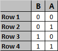
The multiplexing chip has four outputs that control one row each. If both the input A and the input B are pulled low, then the first row is selected. That means only the output line that controls the first row is turned on and the other three outputs of the multiplexing chip are low.
If input A is high and input B is low, then the second row is selected which means that only the second output line is high and the others are low etc.
For full implementation of shift registers and the multiplexing chip, go to SpiData Array.