 |
 |
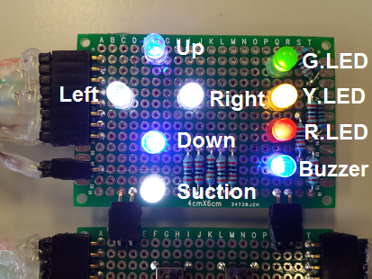 |
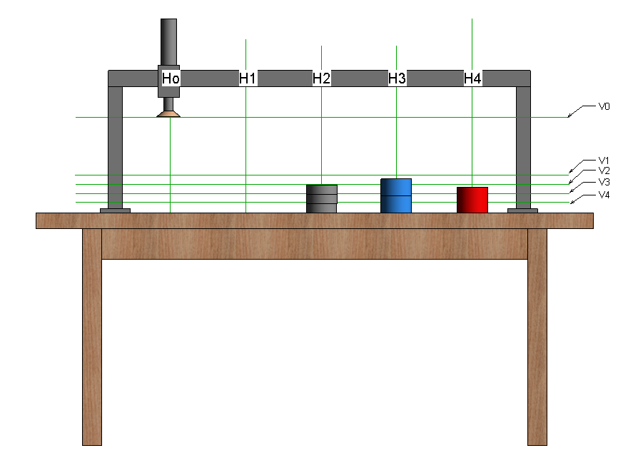
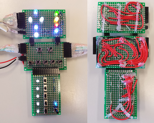
The top panel of the simulator was made to show the outputs of the PLC to the gantry.These outputs can be seen on the labelled picture to the left. |
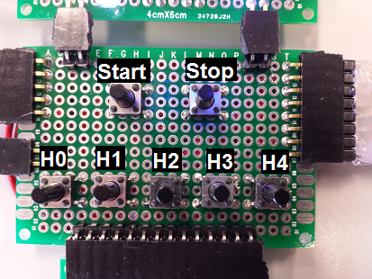
| The middle panel of the simulator was constructed to allow for some of the specified PLC inputs.Namely these are the Start, Stop and horizontal positioning switches as shown on the Right. |
 |
 |
The simulator’s lower panel allows for the remaining PLC inputs which are the vertical positioning switches and the suction cup’s limit switch.These have all been labelled in the diagram to the left. |