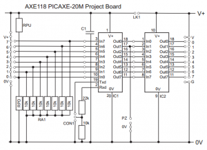
At the heart of the BlackBox motor controller is a PICAXE-20M2 (20M2) micro-controller (uC). The PicAxe system was originally designed to be an educational microcomputer kit, but has now evolved to have thousands of hobbyists using them due to their simplicity and ease of use. For this project we obtained a 32MHz 20M2 controller already installed onto an AXE118 project development PCB. This controller was programmed using Basic where we utilised all 16 of the available input/output pins.
The two main components of the AXEE118 board are the PicAxe 20M2 microcontroller itself and a Darlington transistor array. The Darlington pairs making up this array use two bipolar transistors arranged and packaged in a way that the current from the base of the first transistor is amplified before being fed into the base of the other transistor. This arrangement was invented in 1953 by an engineer called Sidney Darlington while working for Bell Labs. The Darlington array is located on the right of the AXEE118 and is used to switch devices requiring more power than the uC can supply/sink itself.
| PICAXE-20 Project Board (AXE118)
|
PICAXE-20M2
|

Located next to the darlington array on the AXEE118 board is the PICAXE-20M2 microcontroller.
The 20M2’s specifications are:
|
|

PICAXE-20M2 Pins layout
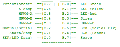
Note pin C.6 is input only on the 20M2. This is due to the internal silicon design of the chip and cannot be altered.
Below is the pin out configuration of the BlackBox’s controller