H-Bridge Circuit used inside the BlackBOX.
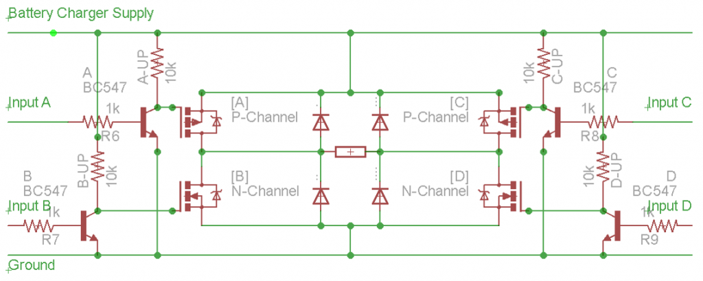
Above is the most advanced H-Bridge design implemented within the BlackBOX, this circuit features a few considerations to make the design more durable and uses MOSFETs (Metal Oxide Semiconductor Field Effect Transistors) as switches where they are controlled by the voltage present at their respective gate terminals.
On each of the gates is a 10k pull-up resistor which ensures that when the BC547 NPN transistors are in cut-off (no input), the voltage level at the gate will be the same as at the supply, thus turning the high side (A&C, P-Channel) MOSFETs off and the low side (B&D, N-Channel) MOSFETs on, grounding both sides of the load. Once ~5v is applied to one of the inputs, the related BC547 transistor will be driven well into saturation and the gate of that MOSFET will be within ~20mV of ground thus switching the related MOSFET from off to on (A&C) or on to off (B&D).
Another consideration in this design is the fact that the motor will represent an inductive load and must be given a path to discharge its magnetic field when switched off. Although the MOSFETs are intrinsically also a diode, these cannot be relied on to tolerate large or sustained currents and external fly-back diodes were added to provide a better path to discharge the inductor on disconnection. These diodes have a forward voltage of 0.5V and can withstand 200A non-repetitive shocks or 3A continuous meaning that they will be activated if either end of the load becomes 0.5V higher than the supply or 0.5V lower than ground.
 |
 |
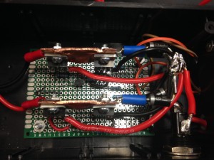 |
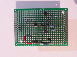
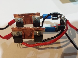
| Control Circuitry | Power Circuitry | Assembled |