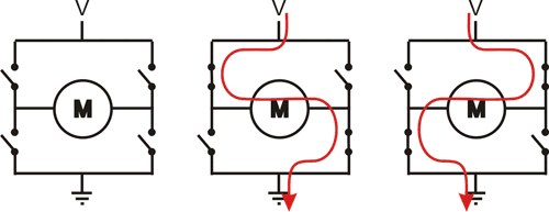
A H-bridge circuit, in general, contains 4 switching elements with a load located in the center which creates a circuit that resemble the letter H: thus its name. This type of circuit is often used to create a bidirectional current flow by using a computer system to rapidly pulse the switching devices and affecting the average voltage across the load.

Functionality of a H-Bridge Circuit
A H-bridge was used in this project to control the motor speed and direction. The program written for this project instructs the PICAXE uC to utilise its hardware level pulse width modulation (hpwm) function to send the desired pulse duty cycles to either Q2 or Q4 for speed control depending upon the direction of operation. Q1 and Q3 will be either on or off as they are not as durable/responsive as Q2 and Q4. Q1 and Q4 works as a set and must always be used with Q2 and Q3 in their off, the same is also true for Q3 and Q2. As the direction of a DC motor is determined by the polarity to its connections, the direction of the motor can then be effectively be controlled by controlling which pair of switches are being switched and the speed/power of the motor will be proportional to the duty cycle of the pulses sent. Pulse width modulation is discussed in more detail here.
General H-Bridge Operations
These drawings show how an H-bridge can change the polarity connecting to the load/motor. This effect is how the BlackBOX controller determines the direction of the 12V DC motor,
