Serial Connection
The serial interface between the PICAXE20M2 and the PC is made when connecting either a AXE027 wire or a AXE026 wire to the pre-installed serial port located onto the AXE118 PCB. The serial communication port will allow the user to send simple serial commands to the micro-controller and allow them to adjust and retrieve the motor set-points, direction and current speed and direction. Note: The PICAXE uses the same serial connection for programming and for human interfacing while running.
The physical interface is shown below as well as the appropriate cables to use.

More information is available here.
Appropriate serial transfer cables


More information is available here.
Serial Communication
Once the serial communicating is made, in order to start controlling the motor via the digital serial communication, the Main switch must be in the start position (up) and the Control Mode switch must be in the digital mode location (down). While in this configuration, the motor speed can no longer be controlled via the potentiometer until the Control Mode switch is returned to the manual position. To go back to manual control, you only have the return the Control mode switch back to the Manual position.
Commands
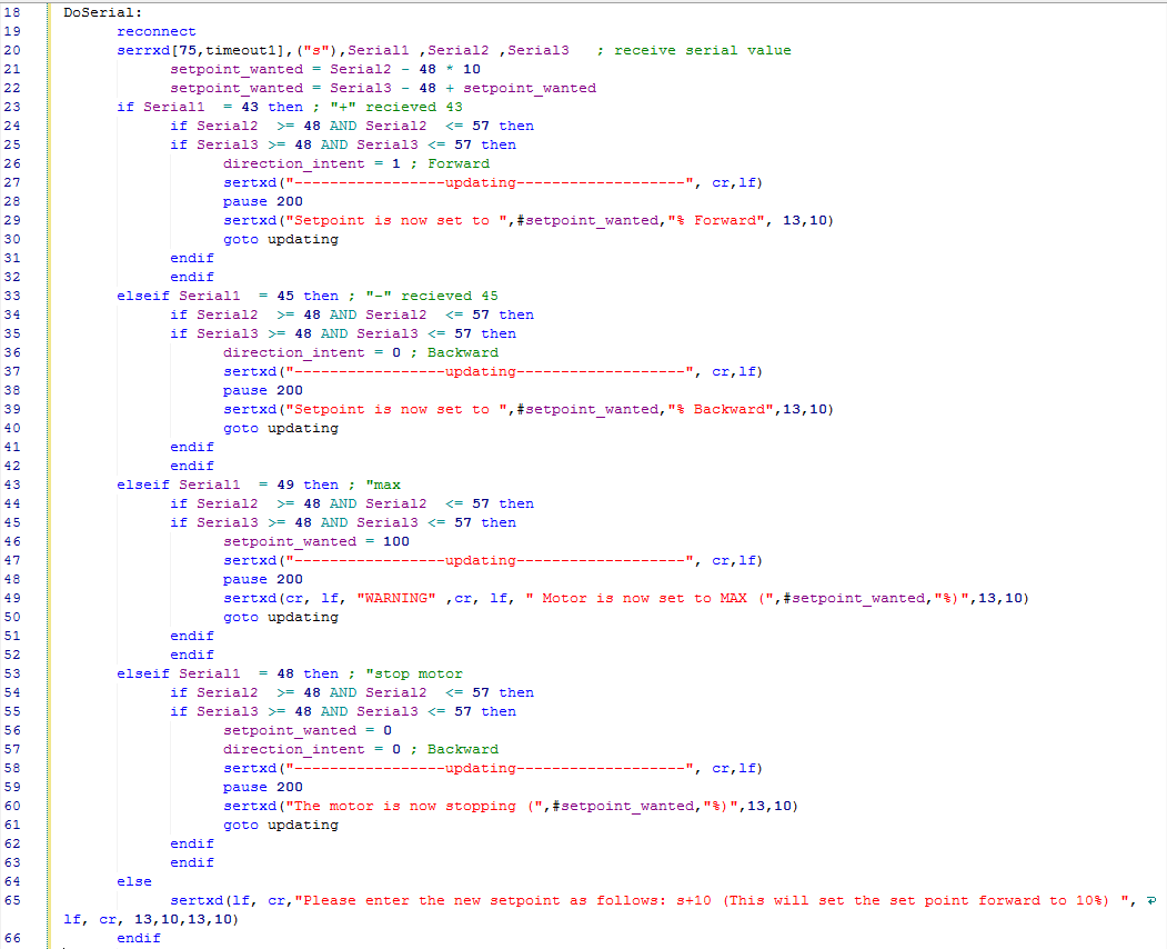
To add a new set-point to the motor controller using the serial connection, commands are entered into the command line. The structure of the command is “s” for telling the micro-computer that a new set-point is desired, then it’s followed by the direction “+” for telling the 20M2 to go forward or “-” for backwards, then it’s followed by 2 digits indicating the speed desired in the form of a percentage.
Examples:
s+20 will set the new set point to 20% forward
s-80 will set the new set point to 80% backward
Special commands:
smax will set the motor to maximum
smin will set the motor to minimum
Data feedback
After sending the command an acknowledgement message will be receive to confirm that the 20M2 actually received and initiated the new set point,
![]()
![]()
![]()
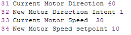
Once the micro-computer initiates the new set-point another confirmation message package will be send back to the user. This information package includes the new set-point and current speed, and the direction of the motor.
Error Messages :
In the event the user sends an invalid command, the 20M2 will send this error message and prompt the user to format the command request correctly.
“Please enter the new set-point as follows: s+10 (This will set the set point forward to 10%) “
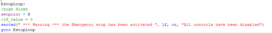
In the event the emergency stop button (deadman switch) was push, this error message will appear:
“All controls have been disabled *** Warning *** the Emergency stop has been activated ”
Codes:
Emergency Stop Button Code