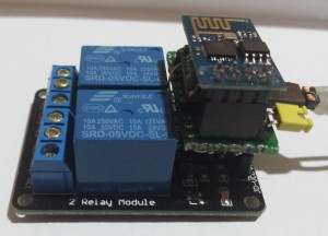
 ESP8266 modules have made wireless connectivity a cheap and easy way of remote controlling almost any device. I thought I’d see how cheaply this could be done with the most basic version, the ESP-01.
With this implementation the web interface’s background colour of each relay is automatically updated to indicate its status, this page is also refreshed periodically in case of multiple users.
| 2-Channel Relay Module | $1.66 | Link | 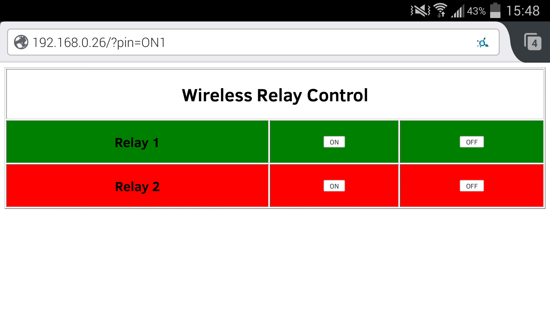 |
| ESP8266 ESP-01 WiFi Module | $2.26 | Link | |
| Buck Converter Module | $0.70 | Link | |
| Transistors,Resistors,etc. | $0.38 | ||
| Total | $5.00 |
This should have just been a matter of interfacing the two modules and editing some sample code but there were a few complications.
- The ESP8266 is strictly 3.3V, requires the use of AT+ commands by default and needs to be wired in a particular way.
- The Relay Module is 5V only and will not work properly with 3.3V logic, this module is also active low.
The solution to the voltage level issues were to standardise on a 5V supply (USB) and to use a paid of transistors (any NPN type, I used BC547) to inverse the logic and to provide ~5V or ~0V to the relay module. A buck converter was used to provide 3.3V for the ESP8266.
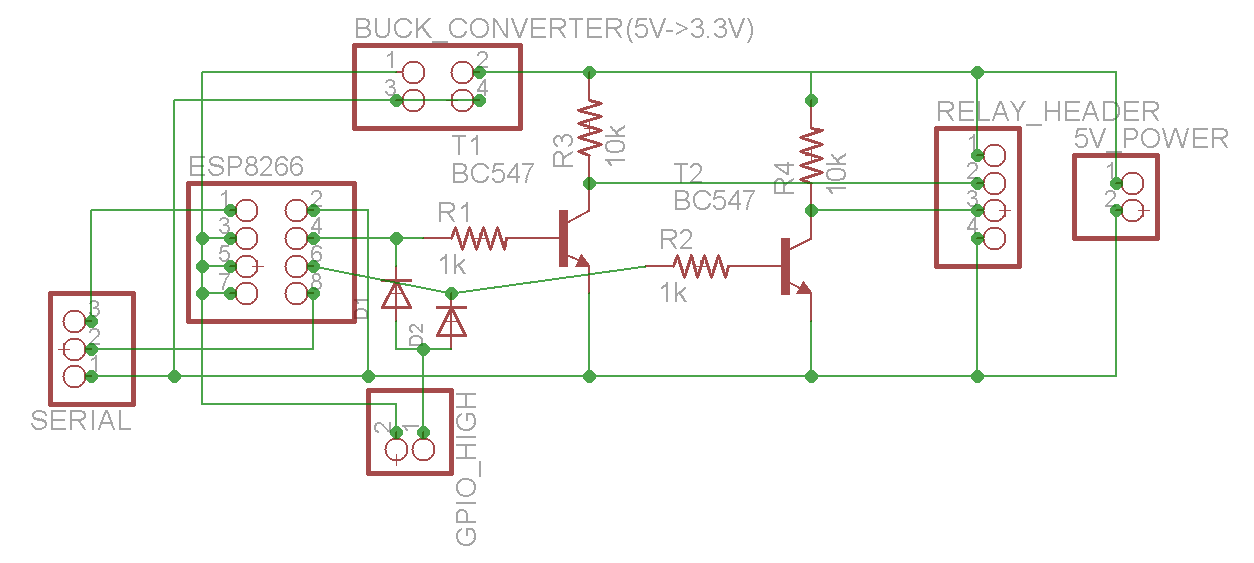
Although the WiFi module uses AT+ commands by default there are great communities at esp8266.com and nodemcu.com which will instruct you how to get the board working, re-flash with nodemcu (Lua interpreter) and code the chip in a nicer environment. For each of these steps you will need a serial connection such as a CH340G ($1.00) or FTDI USB adapter.
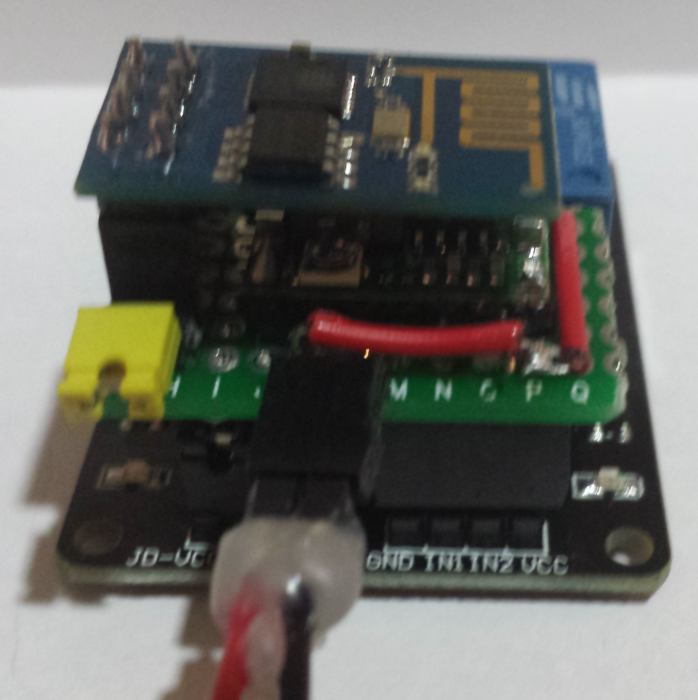
Since GPIO0 needs to be pulled high at boot for the chip to operate normally my current workaround is to use a jumper and diodes to manually pull both GPIO0 and GPIO2 high at boot time then I remove the jumper to allow normal operation. I may revisit this in future depending on the final application.
Here are a few more photos of the assembled unit:

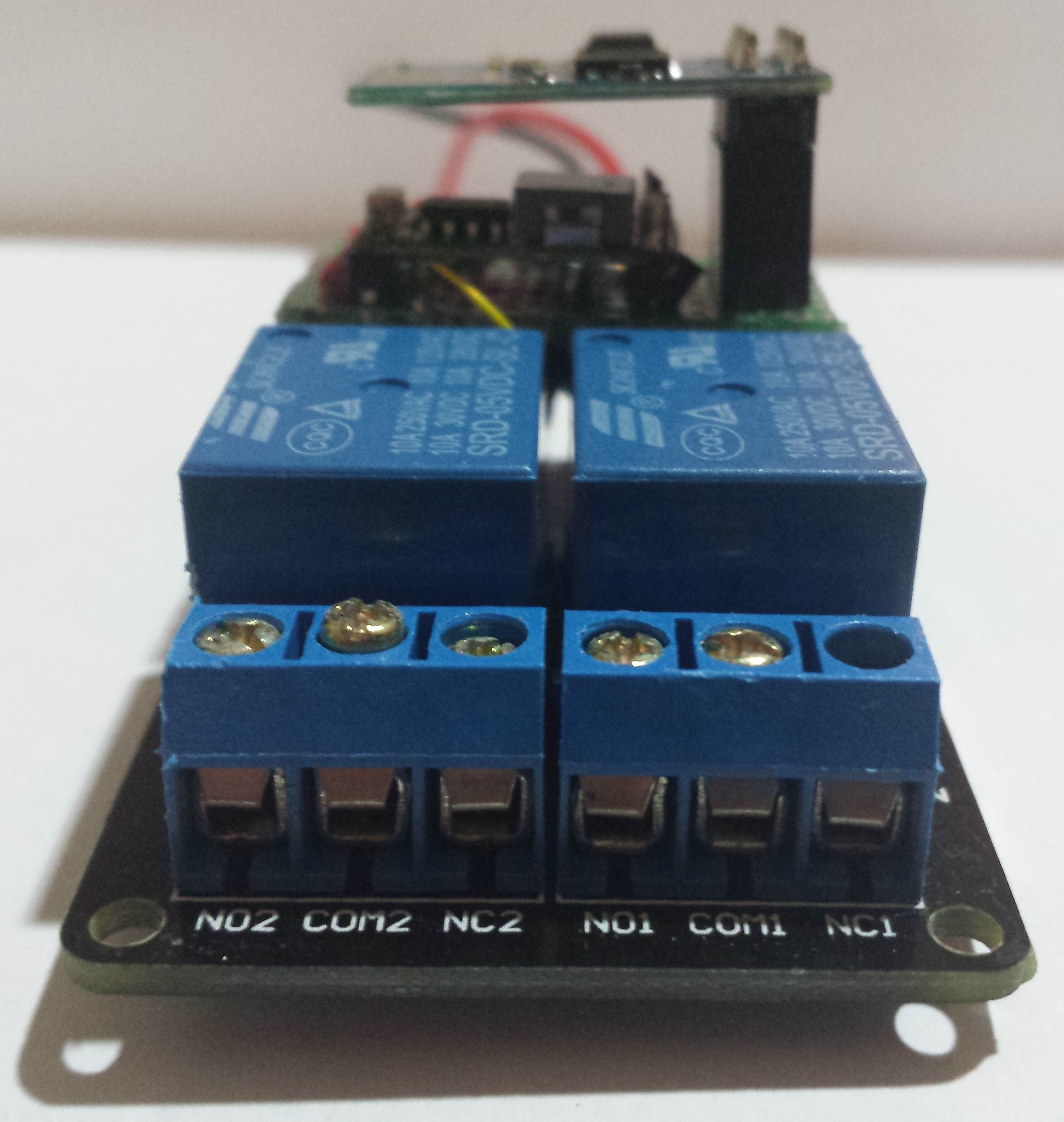

Since I was planning on powering this project over USB I wanted to know the current draw when both relays are activated, in this case it was ~200mA which is well short of the 500mA which is the limit for basic USB ports. It should also be noted that the ESP8266 can draw 300mA under heavy load however it has quite a light load in this project and using a buck converter instead of a linear regulator helps eliminates waste.
Here is the (Lua) code which has been adapted from Rui Santos’ code to make the web page reflect the current status of each relay on loading and to automatically reload the page periodically.
init.lua:
wifi.setmode(wifi.STATION)

wifi.sta.config("NETWORK_NAME","NETWORK_PASSWORD")

print(wifi.sta.getip())

output1 = 3

output2 = 4

gpio0 = "white"

gpio2 = "white"

gpio.mode(output1, gpio.OUTPUT)

gpio.mode(output2, gpio.OUTPUT)

srv=net.createServer(net.TCP)

srv:listen(80,function(conn)

conn:on("receive", function(client,request)

local buf = "";

local _, _, method, path, vars = string.find(request, "([A-Z]+) (.+)?(.+) HTTP");

if(method == nil)then

_, _, method, path = string.find(request, "([A-Z]+) (.+) HTTP");

end

local _GET = {}

if (vars ~= nil)then

for k, v in string.gmatch(vars, "(%w+)=(%w+)&*") do

_GET[k] = v

end

end

local _on,_off = "",""

if(_GET.pin == "ON1")then

gpio0 = "green"

gpio.write(output1, gpio.HIGH);

elseif(_GET.pin == "OFF1")then

gpio0 = "red"

gpio.write(output1, gpio.LOW);

elseif(_GET.pin == "ON2")then

gpio2 = "green"

gpio.write(output2, gpio.HIGH);

elseif(_GET.pin == "OFF2")then

gpio2 = "red"

gpio.write(output2, gpio.LOW);

end

buf = buf.."<html><head><META HTTP-EQUIV='refresh' CONTENT='10'></head><body>";

buf = buf.."<table width='100%' border='1px'><tr><td colspan='3'><center><h1>Wireless Relay Control</h1></center></td></tr>";

buf = buf.."<tr bgcolor=";

buf = buf..gpio0;

buf = buf.."><td><center><h2>Relay 1</h2></center></td><td><center><a href=\"?pin=ON1\"><button>ON</button></a></center></td><td><center><a href=\"?pin=OFF1\"><button>OFF</button></a></center></td>";

buf = buf.."</tr><tr bgcolor=";

buf = buf..gpio2;

buf = buf.."><td><center><h2>Relay 2</h2></center></td><td><center><a href=\"?pin=ON2\"><button>ON</button></a></center></td><td><center><a href=\"?pin=OFF2\"><button>OFF</button></a></center></td>";

buf = buf.."</tr></table></body></html>";

client:send(buf);

client:close();

collectgarbage();

end)

end)
If you would like any more information on this then feel free to leave a comment or otherwise get in touch.