Method of Implementation and Discussion
There are 16 steps in brightness for the LEDs on the Dot Matrix Display. The brightness can be adjusted with a potentiometer. The program reads the AD value of the potentiometer every 100ms so the brightness gets updated 10x a second.
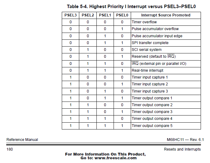
The brightness control is done by doing a PWM on the outputEnable pin on the Dot Matrix Display. But because no PWM pin is mapped out on the 68HC11 board, the hardware PWM function can not be used for this. The next approach was doing a PWM with the output compare function of a hardware timer. The issue with this approach is that the interrupt priority of the timers are lower than the interrupt priority of the SPI.
 [3]
[3]
The display flickered when doing a brightness PWM with a timer because the SPI interrupt had priority over the timer interrupt which resulted in the outputEnable pin to be updated too late.
This issue can be overcome by doing a software PWM inside the SPI interrupt service routine. The Dot Matrix Display has 16 shift registers inside to update. Each shift register controls four rows of LEDs and each row gets selected via multiplexing. Once the first 16 bytes of data get clocked in and latched, the multiplexing enables the next row to receive 16 bytes of data (one byte per shift register). Therefore row 0, 4, 8 and 12 get updated first. With the next 16 bytes, row 1, 5, 9 and 13 get updated etc.
Brightness control is done by doing a custom made PWM inside the SPI interrupt routine. When a relative brightness of 3/16 is calculated, then the outputEnable pin will be high while the first three bytes of SPI data are clocked in and low while the other 13 bytes of data are clocked in. Because each shift register updates four rows of LEDs, the outputEnable pin will be pulse width modulated four times until the entire display is updated completely.
Analog to Digital Conversion
To dynamically control the brightness of the display a task was set up to read from the analog to digital subsystem and store the brightness variable ready for the assembly update interrupt cycle.
Monitor A2D Values with Task
[code]variable Brightness
task BrightnessUpdate
: BrightnessUpdateDo BEGIN ADr1 c@ 16 / 1 + Brightness c! 100 MS AGAIN ;
: StartDoBrightness BrightnessUpdate build BrightnessUpdate ACTIVATE BrightnessUpdateDo ;[/code]
Before these values could be read from the analog to digital register number one (ADr1), the analog subsystem had to first be configured and turned on.
Setup Analog to Digital (A2D) Subsystem
[code] %10000000 OPTION ByteSet ( Enable Analog to Digital )
%00100000 ADCTL c! ( Channel PE0 in ADR1, single channel continuous mode, read from ADr1 )
StartDoBrightness[/code]
With this simple code the A2D subsystem and BrightnessUpdate task work together to manipulate the display’s brightness in a dynamic manner.