
The method used to create the graphics using our program is unique and we call it a byteFrame. Each byteFrame is made of a byte(8bits) by 16 bytes. Therefor a byteFrame is a rectangle of 128 bits that are arranged in a 8 x16 bit pattern as shown below;
1 ByteFrame
0 0 0 0 0 0 0 0
0 0 0 0 0 0 0 0
0 0 0 0 0 0 0 0
0 0 0 0 0 0 0 0
0 0 0 0 0 0 0 0
0 0 0 0 0 0 0 0
0 0 0 0 0 0 0 0
0 0 0 0 0 0 0 0
0 0 0 0 0 0 0 0
0 0 0 0 0 0 0 0
0 0 0 0 0 0 0 0
0 0 0 0 0 0 0 0
0 0 0 0 0 0 0 0
0 0 0 0 0 0 0 0
0 0 0 0 0 0 0 0
0 0 0 0 0 0 0 0
In our program a bit with a value of zero is interpreted by the processor as an open circuit(LED off) where as a bit with a value 1 is interpreted by the processor as a closed circuit (LED on). By using this approach we then set out to create all the ascii symbols and have it store in memory. This proved to be a valuable part of our project but also very time consuming, For example to write a Capital letter “A” in memory, it is created by changing the zero into ones in the desired pattern:
1 ByteFrame with the Capital letter A pattern
0 0 0 0 0 0 0 0
0 0 0 0 0 0 0 0
0 1 1 1 1 0 0 0
1 0 0 0 0 1 0 0
1 0 0 0 0 1 0 0
1 0 0 0 0 1 0 0
1 0 0 0 0 1 0 0
1 0 0 0 0 1 0 0
1 1 1 1 1 1 0 0
1 0 0 0 0 1 0 0
1 0 0 0 0 1 0 0
1 0 0 0 0 1 0 0
1 0 0 0 0 1 0 0
1 0 0 0 0 1 0 0
0 0 0 0 0 0 0 0
0 0 0 0 0 0 0 0
Another convention that our group decided to make is to have the symbol begin on the most significant bit in order to have the pattern against the right most edge of the byteFrame.
This is how each symbol of the ascii table was written however, it proved to be very time consuming. Later our group devised an a ms Excel spread sheet that makes this task much more efficient and reduced errors.
Our approach for retrieving the correct symbol and displaying it when the program calls for it, our group decided to create a text file that has inside it a long list made up of nested IF statements for ascii symbol number as a condition. Furthermore, each IF statement code includes the scrolling information for each letter. This extra bit of code was necessary because some symbols had smaller or greater width then the average symbol. For example the letter I is only 3 columns where as the letter W has 7 columns in total. The extra information is essance is a do loop that calls a scrolling function that ether Scrolled and displayed the symbol from the right or the left. This configuration later allowed for a string to be simply type and stored as a series of ascii values where a function called Print would find the corresponding ascii symbol it print it on the display according to the desired scrolling pattern.
Example of the format for storing, retrieving and displaying the correct symbols in memory for the DMD
dup 66 = if \ if capital A then display A onto the DMD from right or left
0 0 0 0 0 0 0 0
0 0 0 0 0 0 0 0
0 1 1 1 1 0 0 0
1 0 0 0 0 1 0 0
1 0 0 0 0 1 0 0
1 0 0 0 0 1 0 0
1 0 0 0 0 1 0 0
1 0 0 0 0 1 0 0
1 1 1 1 1 1 0 0
1 0 0 0 0 1 0 0
1 0 0 0 0 1 0 0
1 0 0 0 0 1 0 0
1 0 0 0 0 1 0 0
1 0 0 0 0 1 0 0
0 0 0 0 0 0 0 0
0 0 0 0 0 0 0 0
LoadFrame 5 0 do Scroll loop else
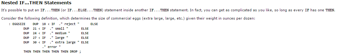
Example of the Nested IF….THEN statement structure used for searching and retrieving the correct symbols
During the course of writing all the symbols, our group had a couple ideas to make it easier. One idea was to a simulator so we can visualize and trouble shoot the coding and the other idea was to create a program that allowed a user to simply draw what they wanted to have displayed and have the codes automatically written.
For more information on the two DMD Simulator click here.
For more information on the DMD Image and Animation Editor click here.
PICTURES AND ANIMATIONS


(Still image unavailable, image is much clearer than it appears above)