Signal Inversion with possible level shift
All the PortB pins from the PICAXE board are going through a Darlington array which means they can only be used as outputs.
The Darlington array also inverts the logic: It lets current flow through its Darlington transistor when the pin of the PICAXE is high which grounds the load attached to the Darlington output. The output is only high when the base of the Darlington array is pulled low and a pull-up resistor is attached (the Darlington is in cut-off).
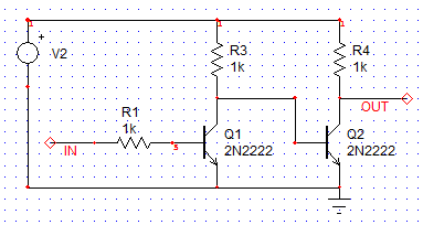
Because the hpwm (Hardware Pulse Width Modulation) function of the PICAXE uses one pin on PortB, that logic inversion of the Darlington array is unwanted. Therefore a logic inverter was created to change the output back to the original logic of the PICAXE pin or even raise the voltage of the output above that of the PICAXE.
Now the logical output of the PICAXE pin corresponds to the output of the converter but can also have its level shifted.
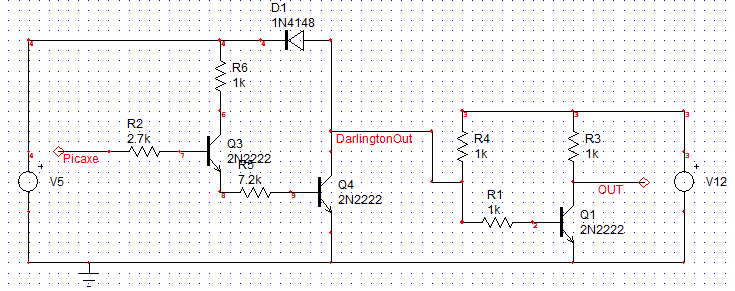
Signal Buffer with possible level shift
When the project needed to be altered to accommodate a single grounding MOSFET for speed control in both direction, the approach taken was to rectify both low-side PWM signals and apply that directly to the MOSFET’s gate. To do this the signal levels needed to be boosted to minimise losses in the MOSFET so the above circuit was used to raise one to 12v and the below circuit was used to buffer the other to 12v also.