To control the speed of the motor, the BlackBOX utilised the inbuilt hardware pulse width modulation (hpwm) function of the PICAXE20M2. However, to make it work properly, a level of research and testing was needed to ensure proper operation. This included learning more about the use of this function, the syntax for proper use and making available the specified pins required to use the hpwm function.
Once the h-bridge had been built and the control circuitry implemented, some testing using the oscilloscope was performed to find a good medium between control resolution and PWM frequency, the result of these tests was dividing the hpwm frequency by 16 which gave good resolution for duty cycle values of 0-1023 for 0-100%.
Click here to learn more about the 20M2 hardware PWM functions and the HPWM function call used in this project.
Below shows how the hardware pulse width modulation was used for this project.
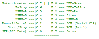
Pin Layout:
Using the 20M2 Manual we found out exactly which pins to use and created the following layout:
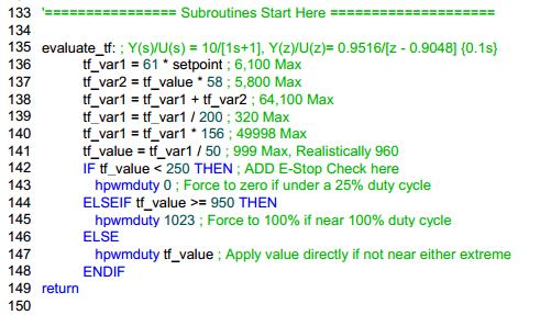
Initialisation:
 This line needed to be altered when changing from a true h-bridge to the improvised implementation used after the eleventh-hour destruction of the h-bridge (relays for direction control and rectified hpwm for N-Channel MOSFET speed control).
Controlling the motor speed using a 1st order transfer function:
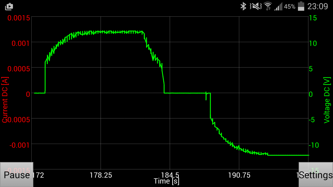
The BlackBOX’s pulse width modulation results (moving average):