
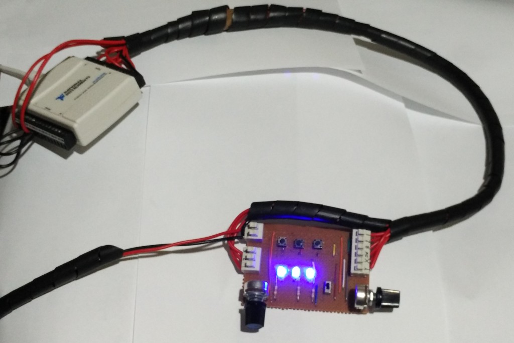
The digital inputs and outputs are accessible/visible from the user’s controller shown below.
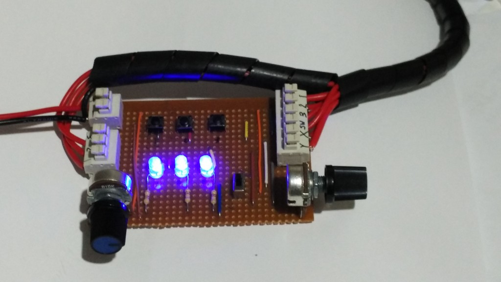
The controller is used by the USB-DAQ which can be connected to a different computer than the output DAQ if desired. The whole user-control setup is shown in the photo below and requires a USB connection only because power and GND for the board can be taken from the USB-DAQ.
Within the program, a parallel loop is used to interact with the user and displays the program’s current Etch-A-Sketch operating mode while also handling record/stop button latching via a feedback node. These values are also stored in local variables for use within the rest of the program. Below is an excerpt of the relevant digital input/output code to be discussed.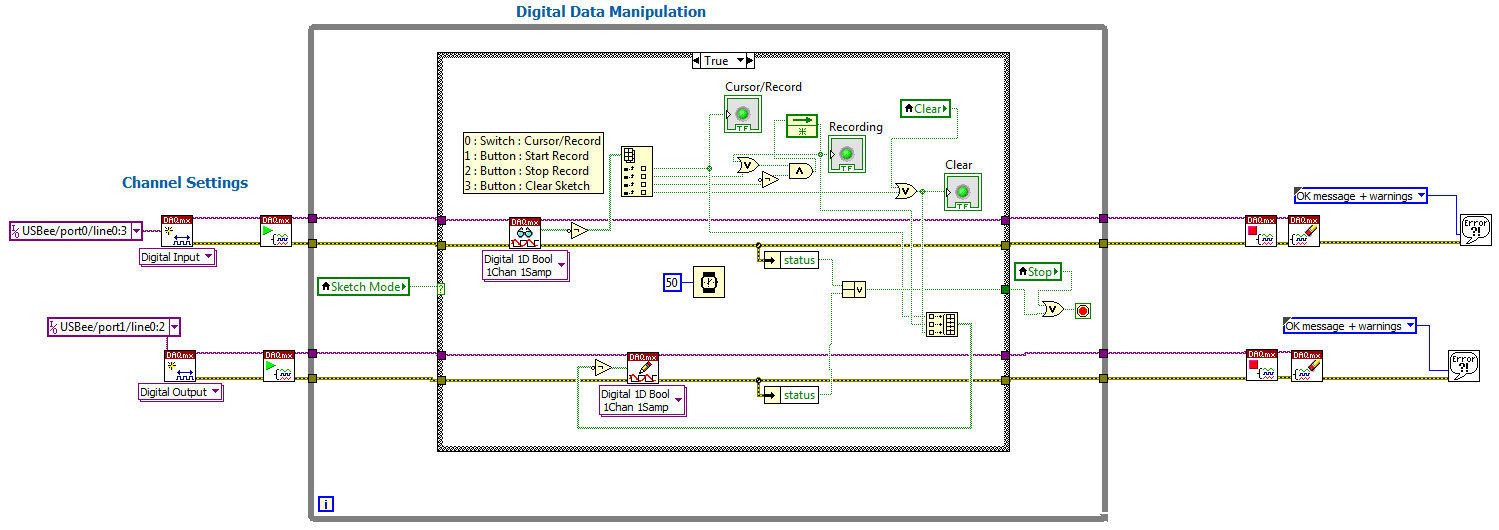
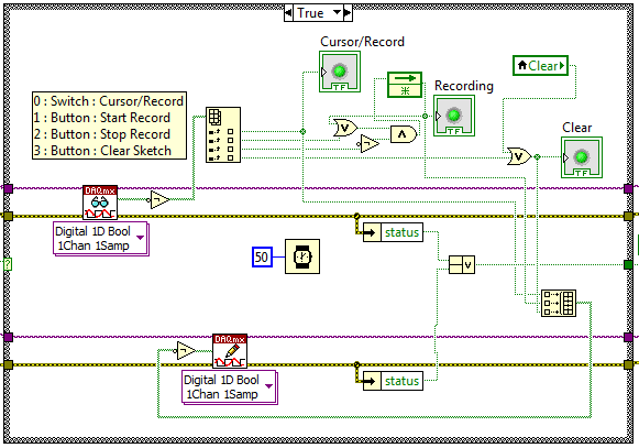
The code on the far left and far right involves setting up and closing the hardware connections. The code in the middle is a continuous loop with the inner most loop only being active whilst the program is in Etch-A-Sketch mode as it is only relevant in that mode. On the right is this code.
The first action on the top left is to read the current values of the switches/buttons, these have been wired as active low so the data is passed through a not operation. The cursor/read switch is stored to a variable and directly outputted, then the start/stop buttons are latched or de-latched depending on the their values (dominant off). Lastly, the clear button is latched if it is pressed. The clear operation is not de-latched here as the latch will be removed once the operation is completed by the main program.