As it is impossible to initially test the operation of the gantry crane while developing its program, it is imperative that the mechanical design, constraints and limitations of the machine are completely understood and accounted for. A single non valid assumption can lead to the machine unable to do its tasks.
The key mechanical constraints used for designing the operational program for the machine are:
- The physical limits constraining the travel and speed of the machine.
- The physical wiring connections made in the inputs and outputs of the PLC IO module
- The physical hardware being used on the machine (type of switches, the exact PLC hardware, etc…
- The location of the switches
The PLC program written for operating this gantry crane is created with only the information provided by the Project 2-gantry apparatus information guidelines.
Physical constraint
The Project-2 guide states that the maximum travel time for the gantry crane is: 5 seconds for the vertical travel time and 15 seconds for the horizontal movement.
It is assumed that the crane can physically move pass the vertical and horizontal limit switches and therefore requires a series of code to initially find the position of the crane.
The Project-2 guide states that it requires only 1 seconds to create the suction necessary to lift the disks. Since we are not sure if the lips of the suction cup will make contact with the disk when the I125.7 switch is circuit is closed, we therefore assume that the Q124.3 output must remain true for the required 1 second duration to insure that the suction will be strong enough to lift and carry the disk every time.
Physical wiring
We assume that all the wiring connections will be in proper working order and strictly adhere to the wiring Project-2 guide.
PLC
The SIMATIC S7-300 universal controller is specially designed for innovative system solutions in manufacturing, specifically the automotive and packaging industries. This modular controller serves as an ideal universal automation system for centralized and decentralized configurations. Safety technology and motion control can be integrated with standard automation into this universal controller. The Siemens S7-314C-2 DP is a Fast, high-performance and versatile Compact PLC with integrated functionality.
| S7-314C-2 DP CPU Specs : • SIMATIC Micro Memory Card (required for operation) • 9-pin Multiple Point Interface (MPI) • 9-pin Digital Point (DP) interface • Digital inputs – 24 • Digital outputs – 16 • Analog inputs – 5 • Analog outputs – 2 • Technological functions – 4counters, 1 Channel for positioning Volts and Currents Input Delay is around 8 µs |
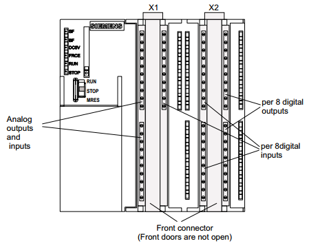 [4] Integrated I/O of the CPU |
Actuators
The actuators used on the gantry project are all controlled by solenoids. these solenoids will let the air flow only if one of the input is true. These inputs are Q124.0 (left), Q124.1(right), Q124.2(up) and Q124.3(down). That is we assume that no other movement will occur other than the small uncontrolled momentum caused when the solenoid outputs are set to false.
Limit Switches
The gantry crane machine is already wired with switches. It has 1 momentary micro limit switch for detecting a disk, 2 push buttons for turning the machine on and off, and 10 reed type switches used to indicate 5 horizontal and vertical positions of the crane onto the gantry apparatus. They are all momentary switches and they can only be relied for determining transient states.
The picture below shows the arrangement of the switches as described in the Project-2 guide.
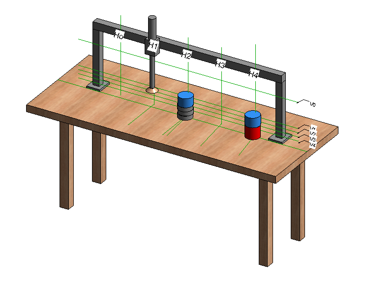
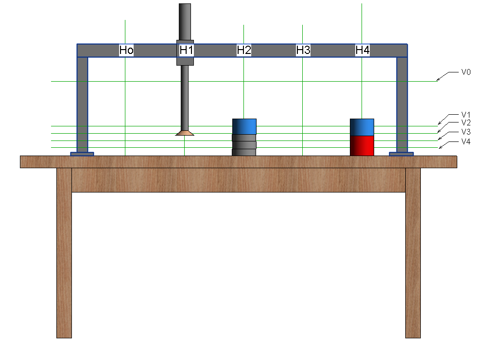
As these switches provide the primary external environment-to-computer interface, it is imperative that they all work perfectly and their locations are placed in a fixed manor at the exact locations describe in the Project-2 guide. Any changes or malfunctions of the switches can result in the crane not being able to complete all the tasks. The most important switches are the vertical switches(V0 – V4). This is because these switches are used to measure the individual disk in the sort-and-place state. The Project-2 design brief provides no information on the actual vertical location of the switches. However, clarification was later given by our lecturer as he is familiar with the construction of the gantry crane apparatus.
The picture below shows the approximate switching location for V4 that corresponds to 1 disks high.
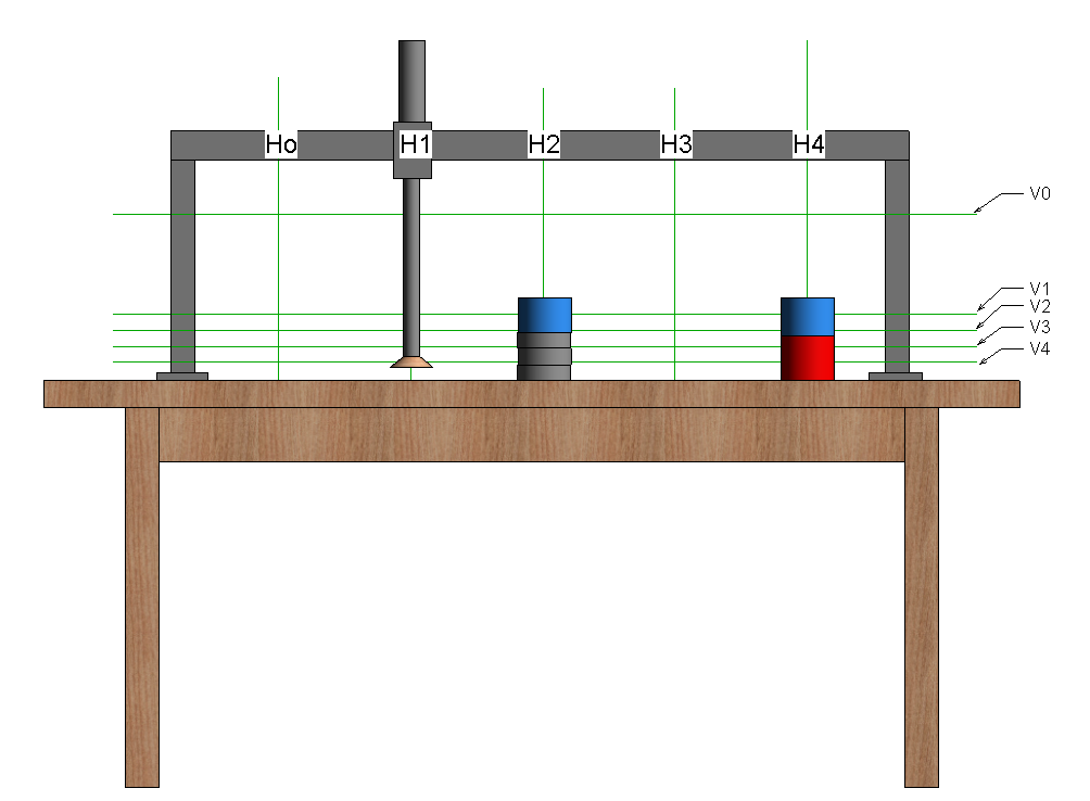
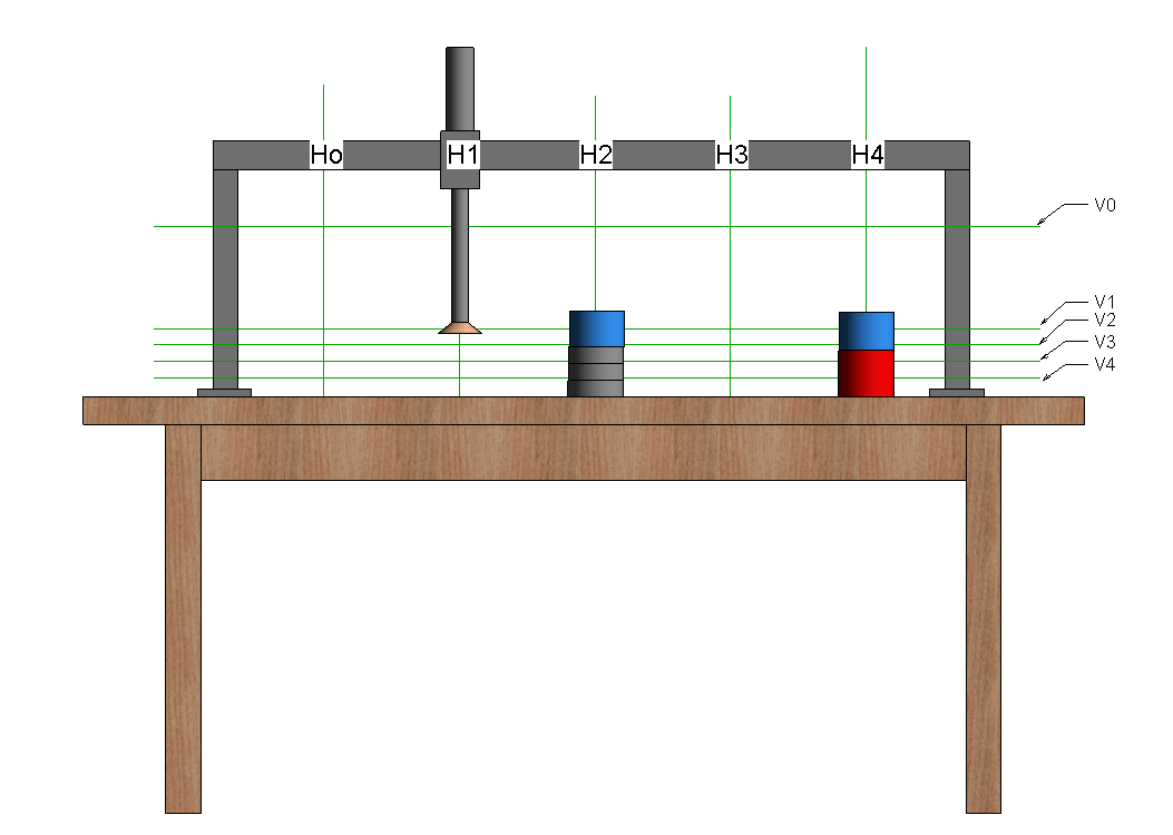
The picture below shows the approximate switching location for V3 that corresponds to 2 disk high.
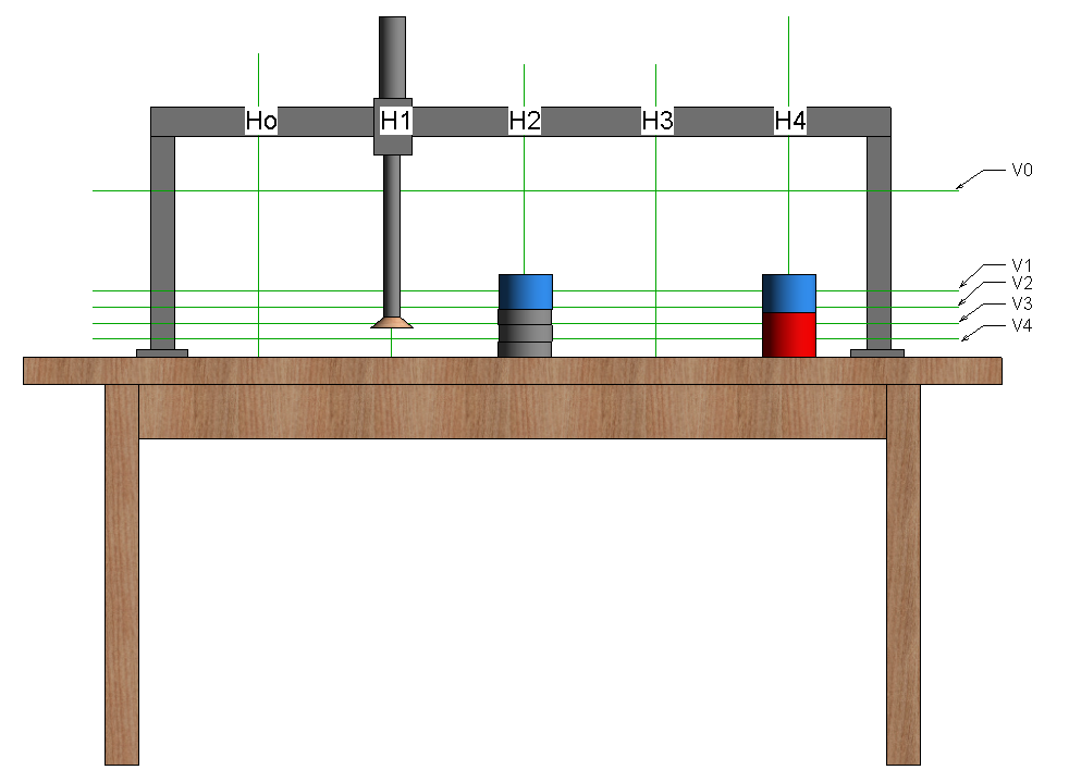
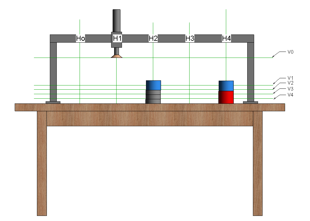
The picture below shows the approximate switching location for V2 that corresponds to 3 disk high.
The picture below shows the approximate switching location for V1 that corresponds to 4 disk high.
To insure proper operation the switches for V2, V3 and V4 must always close before the the suction makes contact with the disk of that corresponding switch. That is if you place a disk of 2 disk height and have the suction moving downwards from the top of the crane, the switch V3 must close at some point before the suction cup make contact with the disk and/or before the V4 reed switch circuit closes.