Shift Registers
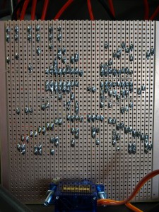
To support a user interfacing with the machine/motor remotely, a simple LED display was created. A total of 16 LEDs were used and installed in a semi circle arrangement onto a PCB board. The LEDs indicate the desired speed of the motor (ie. the desired set-point). Different colors were used (Green, yellow, and red) to provide additional information back to the user about the desired set-point. Sixteen LEDs in total are used. Eight for showing the speed of the motor going forwards and eight LEDs are used to show the backwards speed of the motor.
Whether the user uses the potentiometer or send an ASCII value over the serial connection, the LEDs will directly display the user’s desired speed/set-point.

The LEDs are electrically controlled using two shift register. This was deliberately done to reduce the number of I/O pins used. A shift register receives data as voltage pulses from a serial line and outputs it in parallel in the form of high or low bits. Shift registers can be added to one another and therefore control any number of LEDs with only three output pins: one for serial data, one for clocking the data to the shift register and one for latching the input values to the outputs through the storage register. Attaching several shift registers in series by connecting the carry bit to the serial input of the next shift register results in more than one byte being displayed in parallel. The shift registers can all be clocked with the same two pins whereas the serial data from the microcontroller is only fed to the first shift register.
Serial data is clocked through the shift register by the shift register clock (SRCLK) and data will only be displayed once the storage register (RCLK) is clocked.
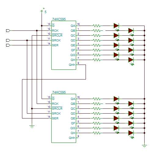 The output pins of the shift registers are 5V, which means that a current limiting resistor is needed in series with the LED. The shift register used (MM74HC595N) only allows a maximum combined current of 70mA for the device, which results in a maximum current of 8.75mA per pin. A resistor of 1k is used as a current limiter which allows about 3.3mA per pin and a total current draw of about 30mA per shift register.
Both the shift register circuit and the servo motor on the same board, the challenge was to keep track of which line to cut and at which point so there would be no short circuits between different signals from the shift registers.
With a total of 16 LEDs to indicate the desired speed in both directions, that leaves a resolution of 12.5%. Implemented is a step size of 12%.
[code]
; —————————————————————————-
; This subroutine sets the LEDs according to the desired motor speed
;
; inputs
; motor_speed desired speed in percent (0%..100%)
; Motor_Reverse_var desired direction of motor (1=reverse, 0=forewards)
; —————————————————————————-
setLEDs:
max_counter = motor_speed/12 ; step size = 12% instead of an ideal of 12.5%
if Motor_Reverse_var = 1 then ; Motor runs in reverse
serData = 0
for counter_2 = 1 to max_counter ; toggle the correct number of binary digits
serData = serData * 2
serData = serData + 1
next counter_2
serData = serData * 256 ; turn forewards LED off by shifting data back by 8 bit
else ; Motor runs forewards
serData = 255
ledSpeed = 0
for counter_2 = max_counter to 7 ; toggle 8 – (correct number of binary digits)
ledSpeed = ledSpeed * 2
ledSpeed = ledSpeed + 1
next counter_2
serData = serData – ledSpeed ; turn forewards LED on
if motor_speed > 95 then ; turn on last LED as well if motor is at max
serData = 0x00FF
endif
endif
gosub clock16BitData ; clock data through shift register
return
[/code]
Servo motor
 A needle is attached to a servo motor to indicate the current speed of the motor.
The servo motor angular position is controlled by applying PWM pulses of specific width. The duration of pulse varies from about 0.5 ms for 0 degree rotation to 2.2 ms for 180 degree rotation. The pulses are recommended to be given at frequencies of about 50Hz to 60Hz.
Due to a cheap device from China being used, the angle of the servo motor does not change linearly with the duty cycle. Therefore adjustments on the code were made to allow linear use of the device.
[code]
; —————————————————————————-
; This subroutine sets the position of the servo needle according to
; the current value of the transfer function
;
; inputs
; direction_action desired speed in percent (0=reverse, 1=forwards)
; tf_value current value of the transfer function (0…1000)
; that represents the current motor speed
; —————————————————————————-
DoServo:
if direction_action = 0 then ; reverse
temp_servo = tf_value / 16 ; servo steps are too small towards the end -> /16 instead of /18
ServoAngle = 50 + temp_servo
else ; forward
temp_servo = 960 – tf_value
temp_servo = temp_servo / 19 ; servo steps are too big -> /19 instead of /18
ServoAngle = temp_servo
endif
ServoPulse = 103 * ServoAngle ; 10.3 us extra pulse width per degree (180 degree max)
ServoPulse = ServoPulse + 4900 ; Zero Position Pulse Width is 554us, not starting at zero
ServoPulse = ServoPulse / 100 ; Calculations are done in 0.1*us, input is *10us
low ServoPin
pauseus ServoPulse
high ServoPin
pause 20
return
[/code]