Access to the designated “hpwm” pins
In order to use the inbuilt Hardware Pulse Width Modulation (hpwm) h-bridge control function the designated pins needed to be used. As one of these pins was connected directly to the Darlington array the output on that pin had been inverted, this was solved by inverting the signal again with another transistor as described under logic/level converters.
Ramping between directional changes
As the motor speed was designated as a magnitude only (pwm duty cycle) it became necessary to consider when a directional crossing was needed.
To do this the program only ever (unless E-Stop) sets a directional intent and a desired setpoint which is then analysed by the program as shown below.
|
If the desired setpoint is in the same direction as the current setpoint then the setpoint is applied directly. If the desired setpoint is not in the same direction as the current setpoint and the transfer function is at zero (motor off) then the desired setpoint and intended direction are safely applied. If the desired setpoint is not in the same direction as the current setpoint and the transfer function is not zero then a setpoint of zero is applied until such time as the transfer function reaches zero before applying the new setpoint and direction. |
[code] ProcessSetpoint: [/code] |
Feedback
While developing the project, interest arose in being able to measure the actual speed of the motor in order to have greater control.
This was investigated by using an infra-red (IR) LED and IR photo-diode pair aligned with the holes in the motor. In this case the LED is also aligned with the photo-diode which is attached to a 5V supply and acts as a current source. The current passed is proportional to the number of photons which land on the LED’s PN junction where individual photons allow individual electrons to pass. To use this concept within the project a large value resistor was attached to the photo-diode in the (1-2 Meg Ohm) with a uC input pin attached at the resistor/photo-diode junction to measure the pulse length.
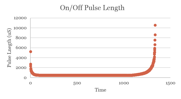
This signal was monitored on the oscilloscope with the motor at full speed where a ~55 uS pulse corresponded to full speed. The uC used has a PulseIn resolution of 10 uS which implied that feedback with this method was possible.
Another uC with the same measurement resolution (Atmega328p) was then used to collect some preliminary date by continually sending the pulse lengths received over serial whilst turning the motor on full speed then off.
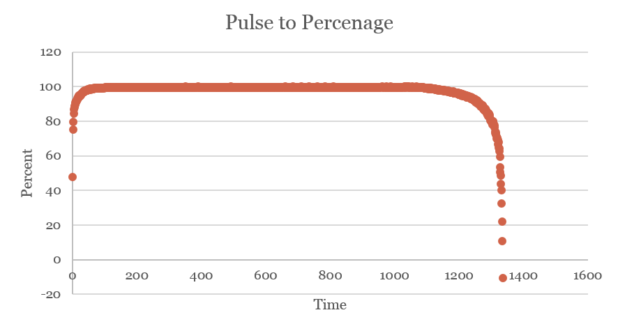 |
This data was then analysed and linearly fitted to represent 0 to 100 percent in integer math as shown below and to the left. If the pulseIn function times out then a zero is returned so this is then fitted to represent zero percent. [code]
|
The 11th hour Redesign
On the weekend before the scheduled presentation of the full H-Bridge, after having working very well over a period of time and during a test of the emergency stop feature (forcing the pwm duty cycle to zero), the H-Bridge broke down. The H-Bridge was then rebuilt after purchasing the closest matching parts available, this H-Bridge worked as anticipated with a light load but also broke down after attaching the motor.
At this time it was the night before presentation and there were no parts available to rebuild the full bridge so a different approach was needed. As the high side MOSFETs are either on or off depending on the polarity of the load it was thought that this signal could be used to control a double pole double throw relay (or two single pole double throw relays). It was also realised that only one of the two low side MOSFETs would receive a pwm signal at a time so rectifying these signals and applying it to a single low side N-Channel MOSFET would allow for speed control.
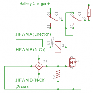
After looking at the available parts, two single pole double throw mechanical relays were found with a 5v control signal drawing a maximum of 4mA, this was a attached directly to one of the uC’s high side signals for direction control. To drive the speed control MOSFET, the pwm signals were stepped up to 12v with the existing converters and rectified before being applied to the gate of the MOSFET with an added pull down resistor in place.
This circuit can be seen on the right and was able to be used with the existing code base with only a slight modification to invert the low side pwm duty cycles (a single digit with the inbuilt hpwm command).
This allowed for an effective motor controller to be demonstrated with a minimum of changes made.
It is theorised that the H-Bridge was destroyed by having one MOSFET conducting whilst the other side of the load was switched off causing one fly-back diode and one MOSFET to conduct the current without any dampening, thus exceeding the conducting MOSFET’s current handling capability.