Introduction:
Inside the BlackBox is a H-bridge circuit. The H-bridge is capable to supply power to the motor with very high speed switching rates and are able to reverse the polarity of the output in order to reverse the direction of the motor.
Design:
Although the design brief for this project mentioned the motor has a 2A rating, a simple experiment was carried out in order to estimate the maximum power consumption. A 12V battery charger was connect in series with a Protek 506 multimeter and in series with the 12V motor. Then resistance was applied to the shaft of the motor and at the instant the motor was energised we obtained a reading of approximately 10 Amps from the Protek 506 when the motor was under load and 8 Amps when the motor was unloaded.
The original design was design using SpiceLT simulation program.
Materials:
4 x 10k Ohm Resistors
4 x 1k Ohm Resistors
4 x BC547 General Purpose NPN Transistors
4 x 1N5404 Diodes (BlackBox version 2, Flyback Diodes)
2 x RF1405 N-Channel MOSFETs
2 x SUP53P06-20 P-Channel MOSFETs
1 x 3A 5x20mm fuse and fuse holder
1 x 50mm x 75m Prototyping circuit board
1 x Black box
Strip connectors, wires, bolts, copper strip, miscellaneous fittings
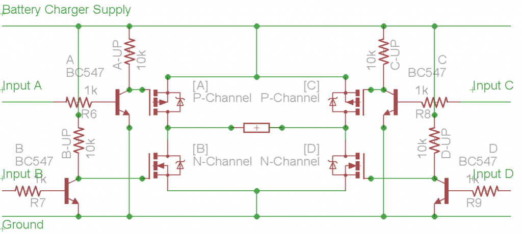
Schematics:
Original Design
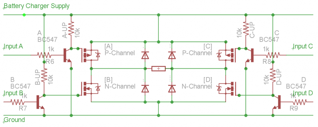
Updated Design with Flyback Diodes
Result:
When commissioning, 2 LEDs with resistors were wired back to back instead of the motor. The original BlackBox H-bridge design work very well. It made the LED’s brightness ramp up and down and when a motor was connected it also drove the motor itself up and down. The design included a copper bus bar to also act as a heat sink and a fuse was installed to helped protect the circuit for over currents. This configuration work well for a long time and was used to continually develop the rest of the control program and some extra features. However, when the added special feature of an electric brake for the emergency button was added in the codes, a problem occurred when the motor was running at full speed then made to suddenly stop pressing onto the E braking button. The back EMF current induced from the motor burn the MOSFET and fuse.
| H-bridge version 1 | H-bridge version 2 |
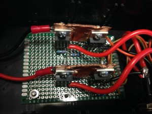 |
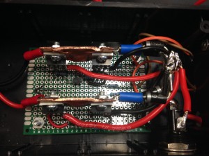 |
To prevent the back EMF current caused from the new E-braking feature to damage the new H-bridge, 4 diodes were added to the design (H-bridge version 2).